Tips & tricks · AI · Everywhere · ~dozens of hours of redrawing a year · 37 min read · in-depth guide, doing it ~3 h
From pencil sketch to computer: what you can actually turn into vectors, CAD, and 3D today
Last reviewed:
In this article
- A typical scenario
- What you can actually get today, and at what quality
- Which programs you can control via MCP, and where things really stand
- Phase 1: Photographing a sketch so it can be vectorized
- Phase 2: Vectorization — from pixels to curves
- Phase 3: Scale calibration — the step where this usually falls apart
- Phase 4: Exporting to a format CAD can open
- Phase 5: From floor plan to a simple 3D model
- Phase 6: Photos of the current state and design variations
- Phase 7: Old plans and PDFs — what you can extract from them
- Phase 8: A presentation board for the client or contractor
- Where the line is
- Security and data
- The most common mistakes
- The best tools
- What you get out of it
- Pro tip
Almost every design starts the same way: with a pencil on paper, on a café receipt, or on a pad of graph paper balanced on someone's knee in a stranger's kitchen. And almost every one of them then hits the same wall — how to get that paper into the computer in a form you can actually keep working with. So you can grab a single line and move it ten centimeters, measure the distance between two walls, and send the file to someone who'll turn it into a real project or a real kitchen counter.
The answer most people try first is the worst one available: photograph the sketch with a phone, drop it into a chat, and type “redraw this nicely for me.” You get an image. It looks good — and it's useless. An image is pixels: you can't measure anything in it, move anything, or export it to CAD. The difference between a picture from a chat and a source file you can keep editing is the core idea behind the guide on treating your brand as a system too — and in technical fields it matters even more. With a brand, a badly generated image costs you time. With a floor plan, it costs you a tradesperson's trust when they build something from it.
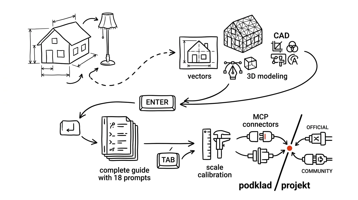
This guide walks the whole chain from paper to a usable file: what can realistically be carried across today and at what quality, how to photograph a sketch so vectorization works, how to turn a raster into curves, how to get the correct scale into them (the most critical step, and the one most often skipped), how to export to a format CAD can open, and how to pull a simple 3D model out of a floor plan. On top of that, an overview of programs you can control through MCP connectors, with an honest line drawn between an official integration and a community project. You can read it phase by phase — each one stands on its own and comes with prompts to copy. And one section is mandatory reading for everyone: where this process ends. Because it ends sooner than most enthusiastic users think.
A typical scenario
Two threads that meet in this guide. They're not random — it's the same technical problem seen from two sides of the table.
Thread A: an interior designer and a hand-drawn floor plan
Tereza does freelance interior design. She sits down with clients on-site and sketches: the floor plan, wall placement options, where the kitchen goes, how people move through the space. She sketches fast, in pencil, on A3 paper, because nothing else works during a meeting — an open laptop kills the conversation.
Back home, she then spends two to three hours redrawing the sketch in CAD. Not that she can't do it — it's just mechanical work: look at the paper, click a line, look at the paper, click a line. At three jobs a month, that's a full working day nobody pays for, because the client is paying for the design, not for tracing.
After adopting the process in this guide, her evening looks different. She photographs the sketch right there at the meeting (square-on, with a tape measure laid across the drawing), has it cleaned up and vectorized at home, calibrates it against the measured length of the outer wall, and exports to DXF. In CAD, she no longer traces — she opens a reference layer with the correct dimensions already in place and draws the clean version straight over it. Two to three hours becomes about forty minutes, and the rest is work she actually wants to do.
Thread B: someone remodeling their kitchen
Martin isn't an architect. He's remodeling the kitchen in the apartment he's lived in for fifteen years, and he has three things: graph paper with a rough floor plan and measurements from a tape measure, twenty phone photos of the current state, and his wife's opinion that “the counter can't go by the window.”
He wants to go see a carpenter. And he knows you don't walk in with a phone photo and “it's sort of an L-shape” — you get a quote full of caveats, and during installation it turns out the dishwasher spot has a soil stack running through it.
The goal isn't for Martin to produce a design. The goal is for him to show up with one PDF that has a floor plan with real dimensions, photos of the current state noting where the utility connections are, and a simple 3D preview of what he has in mind. The carpenter reads it in five minutes, says “that'll work here, not there,” and the conversation starts two levels higher than it otherwise would. That's the whole payoff — not replacing the expert, but showing up prepared for them.
What you can actually get today, and at what quality
Before we get to tools, an honest inventory of your inputs. The same question applies to every one of them: what actually comes out of it, and how much can you trust it. The order runs from the best result to the most deceptive.
A hand sketch: a line drawing
The best input you can have — if it was drawn with digitizing in mind. A clean line drawing, dark pencil or a fine marker on white paper, vectorizes very well: the result is curves that follow your lines closely.
What to trust: the geometry, not the dimensions. Vectorization captures the shape, but it has no way of knowing that wall is 4.2 meters long. You have to supply the scale yourself (phase 3). And a hand-drawn line is a hand-drawn line — it wobbles slightly, corners aren't square, parallel walls aren't parallel. The vector will be exactly as crooked as the original. That's not a flaw in the tool; it's a property of the input.
A photo of a room
A photo is a great input for a description and for design variations, and a poor input for dimensions. A model working from a photo reads what's in the room quite well: where the window is, what the flooring looks like, where a radiator runs, whether the doors slide. It can turn that into a structured summary of the current state that would otherwise take you twenty minutes to write by hand.
What not to trust: any dimension estimated from a photo. Ask the model “how wide is this room” and it will answer — with a guess based on perspective, easily half a meter off. Perspective also distorts things so that even a straight wall in a photo doesn't look straight. A photo is a description and an inspiration, not a measuring tool.
Old paper plans
A floor plan from the eighties out of the previous owner's folder, a copy of a copy with smudged dimensions. You can work with it, but with two kinds of caution.
First, the quality of the original: the older the copy, the more noise, and vectorization will faithfully trace that noise too. Second, and more importantly — an old plan describes a state that may no longer hold true. Over forty years, walls get knocked down, windows get replaced, plumbing gets redone. An old plan is a hypothesis about reality that needs to be verified with a tape measure on-site, not treated as fact.
PDF construction documentation — and why how it was made matters
Here's a distinction that decides whether you're done in five minutes or in two hours. There are two completely different kinds of PDF that look identical:
- A vector PDF was exported from CAD. The lines in it are real lines, the text is real text. You can pull geometry and dimensions straight out of it, open it in Illustrator or Inkscape, and get curves with no vectorization at all. You can tell by checking whether you can search for text in the PDF (try searching for a word from a label) and whether the lines stay sharp when you zoom in a lot.
- A scanned PDF is a photo of paper wrapped in a PDF. You can't search for text in it, and it breaks into pixels when you zoom in. Treat it like any other photo: clean it up, vectorize it, calibrate it.
The first step with any PDF, then, is figuring out which kind you're holding. There's a dedicated prompt for that in phase 7.
Land registry (katastr) records
The Czech land registry (katastr nemovitostí) provides free map data and parcel information — property boundaries, area, land type, parcel numbers. (Most countries have an equivalent public registry or cadastre with a similar role.) For early orientation before a study — where a house fits, how the lot is oriented to the compass points, where the boundaries run — it's a good, legitimate input.
What to trust: identification and the approximate shape of the parcel. What not to trust: boundary precision on the ground. A cadastral map is not a land survey, and the boundary line on the map can differ from the stake in the ground by enough that you can't build a fence on it, let alone a house. As soon as the placement of a structure is being decided, a licensed surveyor with a staking-out report takes over — no software can substitute for that.
Point clouds and phone LiDAR scans
Newer iPhones and iPads with a LiDAR sensor can scan a room, and a number of apps turn that into a floor plan or a 3D model. Export formats tend to be generous — from PDF and PNG through DXF for CAD to OBJ, USDZ, or IFC.
Accuracy: according to tests and manufacturer specs, a carefully captured scan typically lands within a few centimeters of error. That's usable for a layout study and for estimating how much fits where. It is not usable for custom manufacturing to the millimeter — a kitchen counter doesn't get built from a phone scan. Someone comes to re-measure before production anyway, and that's as it should be.
The most useful setup is a combination: use the scan as a fast baseline for the overall shape — including the irregularities of old apartments, which are miserable to measure by hand — plus manual re-measurement of the key dimensions to check the scan against.
Summary table of inputs
| Input | What you actually get out of it | What processes it next |
|---|---|---|
| Hand sketch, dark pencil | Vector paths true to the shape, no scale | Vectorization → SVG/DXF → CAD, 3D |
| Photo of a room | Structured description of the state, reference for variations | Description for the brief, image variations as a moodboard |
| Old paper plan | Original layout, transcribed dimensions and text, a hypothesis about the state | Vectorization + on-site verification with a tape measure |
| Vector PDF from CAD | Real lines and text with no quality loss | Open directly in a vector editor, export to DXF |
| Scanned PDF | Raster, same as any other photo | Clean up → vectorize → calibrate |
| Land registry record | Parcel shape and identification, orientation | Reference for a study, never for staking out boundaries |
| Phone LiDAR scan | Floor plan and rough 3D model, accurate to a few centimeters | Layout baseline, supplemented with manual measurements |
| Image generated from a chat | Visual impression, nothing more | Moodboard, communicating a mood — not reference material |
Which programs you can control via MCP, and where things really stand
MCP is the protocol tools and data use to connect to a model — covered in more depth in the overview of connectors and tools. In practice it means Claude doesn't just talk about Blender — it can actually do something inside it.
There's a critical distinction that gets lost in the excited YouTube videos: an official connector from the software's own maker deserves a different level of trust than a community project off GitHub. An official connector runs under the responsibility of the company that built it, goes through their own approval process, and you turn it on with a click in a connector directory. A community MCP server is third-party software you download and run on your own machine — with access to your files, and often the ability to run code inside your design program. These aren't bad projects; some are excellent. But the responsibility for what you run is yours.
Overview as of August 2026
| Tool | Status | What it can actually do via MCP | What it's for in this chain |
|---|---|---|---|
| Adobe for Creativity | Official connector | Dozens of tools across Creative Cloud — photo editing, raster vectorization, document work and exports, Firefly generation | Cleaning up the sketch photo, vectorization, the presentation board |
| Affinity by Canva | Official connector | Batch production tasks: bulk image edits, layer renaming, export | Processing a series of condition photos, prepping reference material |
| Canva | Official connector | Creating and editing designs, working with templates and brand kits, export | A quick presentation board for the client |
| SketchUp | Official connector (Trimble) | Builds geometry from a brief and reference images, including sketches and floor plans; returns a .skp file and keeps version history | A simple massing model and 3D preview from a floor plan |
| Autodesk Fusion | Official connector | Creating and editing 3D models, operations through Fusion's own interface, file export; requires a Fusion subscription | More precise 3D, parts, and custom furniture |
| Blender | Official connector | Natural-language access to Blender's Python interface, scene analysis and tuning, batch edits | Turning a floor plan into massing, batch operations on a scene |
| Rhino and Grasshopper | Official, free connector from McNeel (Rhino MCP Platform) | Reading file contents, creating geometry, running commands, writing and editing scripts, building Grasshopper definitions | Precise curve geometry, parametric variations |
| Revit | Official technical preview from Autodesk (Revit 2027) | Read-only for now — querying the model, reports, navigation; no writing to the model | Checking and extracting data from a model, not drawing |
| FreeCAD | Community project | Creating documents, inserting and editing objects, running Python code inside the app | A free CAD path for technically comfortable users |
| AutoCAD | I could not find a verified official MCP connector at the time of writing | Community servers of varying quality exist; Autodesk's only official server is one for accessing product help | You get into AutoCAD via a file (DXF/DWG), not via a connector |
| Figma | Official MCP server from Figma | Structured design access for coding agents — components, variables, links to code | More for interface design than construction work |
| Illustrator, Inkscape locally | No connector, but a batch mode | Illustrator via scripting, Inkscape via the command line — Claude Code can drive both | Batch vectorization of dozens of sketches |
A few notes the table doesn't capture, and that matter:
Blender and Revit each have two layers. Alongside the official connector, both also have an older, widely used community project — for Blender that's blender-mcp, and for Revit there are several separate servers. The community versions often do more (for Revit, for instance, they can write to the model, which the official preview can't do yet), and that's exactly why they call for more caution: a server that's allowed to change a live model deserves a backup beforehand and its own test file.
With Rhino, it's the opposite of what most people expect. While community servers were multiplying, McNeel shipped its own free platform — so reach for the official route here, even if a search turns up five GitHub projects first.
What I couldn't confirm: an official MCP connector for AutoCAD from Autodesk (only an official server over their help docs exists, plus a number of community projects), an official connector for ArchiCAD, and an official connector for layout work in Affinity beyond the batch production tasks described above. Where I don't have confirmation, this article doesn't claim anything — and I'd recommend the same stance for you: before you run something against your own project, find the maker's own page, not just a video on social media.
One last practical note on environment: for individual tasks, a regular chat with a connector is enough, but once you're working across a folder of files — dozens of site photos, a series of sketches, a batch export — that's a job for Claude Cowork or Claude Code. The differences between those modes of use are covered in the beginner's introduction.
Phase 1: Photographing a sketch so it can be vectorized
This is the most practical chapter in the whole guide, and also the one everyone skips. Nine out of ten failed vectorizations aren't a software problem — they're a two-second mistake made while taking the photo. Vectorization does nothing more than look for the boundary between dark and light. Hand it a photo where the shadow is darker than the pencil line, and it traces the shadow.
What a sketch that vectorizes well looks like
- A dark line. A fine black marker or a soft pencil pressed firmly enough that the line is genuinely black, not gray. A hard HB pencil drawn lightly is the worst possible combination for vectorization: the line ends up lighter than the paper's own background noise.
- Clean white paper with no grid. Graph paper is comfortable to sketch on, but vectorization traces the grid too, and you end up erasing a thousand little squares. If you do use graph paper, use a bold marker so the contrast between the drawing and the grid is strong.
- One layer of information. Dimensions, notes, and wall hatching get vectorized too. If you want a clean outline of the layout, keep labels off the drawing or use a different color for them.
- Closed outlines. Lines that almost meet but don't quite touch create an open outline in CAD that can't be filled or used as a surface. Close your corners.
- One known dimension right on the drawing. Write the actual measured length next to one wall, or better yet, lay a tape measure across the paper and photograph that. This one piece of data decides whether the drawing can be calibrated or stays a picture forever.
How to photograph it
- Straight down, square-on. Camera parallel to the paper, not at an angle. A tilted photo means trapezoidal distortion that turns a right angle into eighty-five degrees — and that error propagates into every dimension downstream.
- Even light, no shadows. Ideally next to a window in daylight, with the paper turned so there's no shadow from you and no glare on it. A flash does more harm than good.
- The whole sheet in frame, flat, not curled. A cropped sketch is hard to straighten out, and a curled sheet bends the lines and creates shadows.
- Highest resolution, no filters. Portrait mode and phone “enhancements” do things that hurt vectorization.
A practical trick: most phones have a document-scanning feature built into Notes or Files. It does two things for free — it straightens the perspective and boosts the contrast. For this job, that's usually a better starting point than a plain photo.
First prompt: checking whether the photo is usable
Before you run vectorization, have the photo assessed. It saves you a round of tuning the tool's settings when the problem is actually in the source.
I'm attaching a photo of a hand-drawn floor plan sketch that I want to vectorize
and bring into CAD. Assess it as input for vectorization, not as a drawing.

Go through this in order:
1. Contrast between the line and the paper — is the drawing dark enough, or is
   there a risk that vectorization will lose the line?
2. Shadows and uneven lighting — where exactly in the photo is this a problem?
3. Perspective — is the photo square-on, or is the paper trapezoidal? Estimate
   how much.
4. Distracting elements — paper grid, notes, hatching, fingers in frame,
   a stapler.
5. Is at least one dimension in the drawing legible, one I could calibrate the
   scale against? If so, state it.

End with a clear verdict: either “usable, go ahead” or “retake it,” with
a specific instruction on what to do differently. Don't try to flatter the
photo — I need the truth before I build anything on top of it.
You'll get an assessment and, most importantly, a verdict. Models tend to be agreeable, which is why the prompt explicitly demands a harsh judgment — without it, you'll get “the photo's fine, just watch the shadows” even for a photo that's useless. When the verdict is “retake it,” retake it.
Second prompt: cleaning up the photo before vectorization
Cleaning up means: straighten, crop, boost the contrast so the line is black and the paper is white, and remove noise. With the Adobe connector, you can request all of this in a single prompt.
Prepare the attached photo of a hand-drawn sketch for vectorization. The goal
isn't a pretty picture — it's the cleanest possible black-and-white line
drawing.

Do this:
1. Level the horizon and correct the perspective so the paper's edges are
   vertical and horizontal.
2. Crop to the paper, with a minimal margin.
3. Increase contrast and exposure so the paper is pure white and the line is as
   dark as possible. Target look: a scanned document, not a photo.
4. Suppress noise and paper texture.
5. Keep the resolution — don't downscale.

After each edit, tell me what you did and why. At the end, show the result and
flag any spots where the line got lost or blended into the background while
you were boosting contrast.
You'll get an edited image plus a description of the steps. Check exactly that last part — overdone contrast can wipe out a thin pencil line entirely, which you won't notice glancing at a preview, but it shows up as gaps in the outline after vectorization. If the line is disappearing, back off the contrast and clean up the remaining noise by hand instead.
Phase 2: Vectorization — from pixels to curves
What it actually is, and why the whole process rests on it
A raster image is a grid of colored dots. Nothing more. Zoom in and you see squares. To change anything in it, you're repainting dots.
A vector drawing is a description of shapes: “a line from here to there,” “a curve with these control points.” You can zoom in as far as you like, measure it, grab a single point and move it, and export it to formats CAD and cutting machines understand. Vectorization is the one step that changes what your reference material actually is — it turns a picture into data.
Vectorization isn't magic, though: it doesn't turn a hand sketch into a technical drawing, only into curves that copy the hand-drawn line, wobble and all. A clean drawing only comes from tracing over it in CAD — except now you're not guessing where the lines should go.
Three routes, and when to use which
The Adobe connector. The most convenient option if you're already working in Adobe: you request vectorization in chat as one step among others and move straight into export or layout — the whole path in a single conversation.
Illustrator and its Image Trace. The most control over the result: presets for line art, manual tuning of threshold and smoothness, a preview before you commit. When a lot rides on the outcome, this is the way to go.
Inkscape. Free, runs everywhere, and the best choice for two situations: when you don't want to pay for anything extra, and when you need to process a batch. Vectorization lives under the Path menu as Trace Bitmap; for line art, use the brightness threshold, since it distinguishes only between dark and light — exactly what you want here. That's followed by simplifying the paths and exporting. And because Inkscape can be driven from the command line, batch-processing thirty sketches is a job for Claude Code, not your mouse.
Prompt: batch-vectorizing a folder of sketches
This prompt is written for Claude Code or Cowork working across a folder of photos. It's the single highest-value trick in this whole guide if you sketch regularly.
I have a folder at [folder path] full of photos of hand-drawn floor plan
sketches, JPG format. I want to batch-convert them into vector SVGs using
Inkscape, which I have installed.

Steps:
1. First, tell me how many files you found and what resolution they're at.
   Don't change anything yet.
2. Propose an Inkscape command that traces the bitmap using a brightness
   threshold, and explain each parameter in one sentence.
3. Run it on ONE file that I choose first, and show me the result. Never
   overwrite the originals — save outputs into a subfolder called vectors.
4. Once I confirm the result looks right, process the rest as a batch.
5. At the end, give me a table: file, number of resulting paths, output size,
   and flag any where the path count looks suspiciously high — that usually
   means noise got vectorized too.

Don't touch anything outside this folder.
You'll get an overview, one test output to approve, and only then the batch — batch operations only run after a demo on a single piece. A suspiciously high path count is the best signal that something went wrong: a clean floor plan has dozens of paths, not thousands.
Prompt: assessing and cleaning up the resulting curves
I'm attaching the result of vectorizing a hand-drawn floor plan sketch (SVG)
alongside the original photo. Compare them and tell me what needs fixing
before I use this as reference material in CAD.

Focus on:
1. Missing line segments — places where the outline didn't close.
2. Doubled outlines — vectorization often turns one line into two, because it
   traces both of its edges. Where did that happen?
3. Leftover noise: small paths that aren't part of the drawing.
4. Text and dimensions — did they get vectorized as curves? Those are better
   deleted and retyped later as real text.
5. Redundant points on curves that could be simplified.

For each point, tell me whether I should fix it in a graphic editor or later
while tracing in CAD. Don't rewrite the file for me — I want a list first.
You'll get a list of issues and recommendations on where to fix them. A doubled outline is the most common surprise — anyone who isn't expecting it wonders why every wall has two lines half a millimeter apart. For a line drawing, that's normal behavior.
Phase 3: Scale calibration — the step where this usually falls apart
A vectorized sketch is nice-looking and useless until it has a scale. The vector knows a line segment measures 847 units. It has no way of knowing that's actually 4.2 meters in reality.
Without calibration, a vector is just a nicer-looking picture. With calibration, it's reference material you can actually build on. The difference comes down to one number and five minutes of work.
The principle: one verified dimension
The method is simple and it always works:
- Somewhere on the sketch there's a distance you physically measured with a tape measure — say, the inside length of the outer wall, 4.20 m. The longer, the better: error washes out over a longer span.
- In the vector editor, you measure that same distance in the file's units.
- You calculate the ratio and scale the whole drawing by it.
- You measure a different, independent dimension that you also measured with a tape measure, and compare.
That fourth step is the entire safety net. If the second dimension lines up within a centimeter or two, the calibration is good. If it's off by ten centimeters, the problem isn't the math — it's that the photo wasn't square-on, and the drawing is distorted into a trapezoid. The fix isn't recalculating; it's retaking the photo.
Prompt: calculating and checking the scale
I'm calibrating the scale of a vectorized floor plan sketch. Help me
calculate this, and more importantly, verify it.

Data:
- Reference dimension measured on-site with a tape measure: [e.g. inside
  length of the south wall = 4.20 m]
- That same dimension measured in the vector editor: [e.g. 847 px]
- Control dimension measured on-site: [e.g. width of the door opening = 0.80 m]
- That same control dimension in the vector: [e.g. 158 px]

Do this:
1. Calculate the scale from the reference dimension — how many meters
   correspond to one unit in the file, and what factor should I scale the
   drawing by so that 1 unit = 1 mm.
2. Apply that scale to the control dimension and tell me what length that
   would produce.
3. Compare it to the measured value and calculate the deviation in
   millimeters and in percent.
4. Assess: up to what deviation is this reference material usable for a
   layout study, and beyond what point does it need to be retaken or
   re-measured? Explain your reasoning.

Show me the intermediate calculations so I can double-check them myself.
You'll get a coefficient, a control recalculation, and a deviation. Always ask for the intermediate calculations — a multiplication can be done wrong too, and a number with no working is hard to check. Practical guideline: for a hand sketch, a deviation of up to roughly two percent is normal and fine for layout thinking; above five percent, there's an error somewhere that isn't worth carrying forward.
What to do when the reference dimension is missing
This happens constantly: the sketch is done, you're home, and you realize you never wrote down a single real-world length. There are three options, ranked from best to worst:
- Go back and measure it. Boring, but the only honest option.
- Use a dimension that's standardized or verifiable some other way. A standard door opening, the width of a stair tread, a stud spacing. Risk: “standard” means nothing in an old building.
- Derive it from another source — the land registry or an old plan with a dimension on it. Least accurate, but good enough for a first pass.
What never to do: let the model estimate a dimension from a photo. It will answer confidently, and it will be wrong — and that error will propagate into everything you build on top of this reference.
Prompt: a checklist of dimensions to verify on-site
A useful move: have a list generated of dimensions you still need to measure, before you leave the site.
I'm attaching a floor plan sketch [description: 3-bedroom apartment, a
prefab-panel building, I'm measuring for a kitchen redesign].

Build me a checklist of dimensions I need to measure with a tape measure
on-site to turn this sketch into usable reference material. Rank them by
importance, and for each one, note:
- exactly what to measure and from where to where,
- why that dimension matters,
- how much inaccuracy is still fine, and at what point it becomes a problem.

Don't forget the things people commonly forget: ceiling heights, sill
heights, the position and height of water, drain, gas, and electrical
connections, door swing direction, radiator placement, clearance around open
cabinet doors, and out-of-square corners.

I want the output as a table I can print and take with me, with a blank
column for the measured value.
You'll get a printable table. This prompt saves more time than any other in the article — a second trip to the site over one forgotten dimension costs half a day. Adjust the list after your first site visit and reuse it every time.
Phase 4: Exporting to a format CAD can open
You have the vector, the scale checks out. Now you need to get it into the program you'll actually draw in. And there are three formats to choose between.
SVG, DXF, DWG — what's what
- SVG is the vector format of the graphics world: every graphic editor and browser can open it, but CAD programs handle it inconsistently — sometimes fine, sometimes with a strange scale, sometimes not at all. A great intermediate step, a poor final destination.
- DXF is the CAD interchange format, designed specifically so different programs can hand data back and forth. Practically every CAD program can open it, including the free ones. For this chain, it's the default choice.
- DWG is AutoCAD's native format. It's the most common format in professional practice, but it's a closed format that's harder to write to from outside. Practical approach: export DXF and leave any conversion to DWG to whoever works in AutoCAD — they open the DXF and save as DWG in one click.
Concretely: Inkscape can save a vector as DXF in an older, compatible version, which is more than enough for tracing material. Illustrator exports to DXF too. So the path “SVG from vectorization → DXF → CAD” works whether you're on the free tools or the paid ones.
What to watch out for on export
Three things that regularly spoil the moment:
- Units. Vector editors work in pixels or points, CAD works in millimeters. If the units don't convert correctly on export, the drawing opens in CAD a thousand times too small or too large. Fix it either at export time or by rescaling after opening — which is exactly why you always measure one known dimension first thing in CAD.
- Curves versus line segments. Vectorization produces Bézier curves, and some CAD programs break them down into a lot of short line segments on DXF import. For reference material you're going to trace over anyway, that's not a problem — but it's one more reason a vectorized sketch is reference material, not the final result.
- Layers. Everything arrives in CAD on a single layer. It's worth renaming it to something like reference-sketch right away, giving it a gray color, and locking it. Then you draw the clean version over it without any risk of accidentally grabbing a point from the reference layer.
Prompt: preparing the export and a checklist
I have a vectorized and calibrated floor plan sketch in SVG (1 unit = 1 mm),
and I need to get it into [name of CAD program] as reference material for
tracing.

Prepare me a process and a checklist:
1. Which export format do you recommend for this goal and why — and what's
   the second-best option if the first one fails?
2. What to watch for with units, so the drawing comes in at the right size.
3. How to clean up the file before export: what to delete, what to merge,
   what to convert.
4. What to do right after opening it in CAD — how do I verify the scale is
   correct, and how do I lock the reference layer.
5. The three most common problems with this kind of transfer and how to
   recognize them.

Keep it short and in steps — I want to use this as a checklist card, not
read it like an article.
You'll get a usable card. Check one thing yourself: menu item names differ between program versions, and the model will happily guess at them. Treat the process as a map — look up the actual command names inside the program.
Prompt: checking the file after import
I've opened the vectorized reference material in CAD and I want to make sure
it's usable. Walk me through checking it.

Give me a list of checks to run, ranked by importance, and for each one note
what result is fine and what result means there's a problem:
- checking the scale against a known dimension,
- checking squareness where corners should be square,
- checking that the drawing is complete and nothing got lost,
- checking the element count (a sign of curves having broken apart),
- checking the position relative to the coordinate origin.

For each check, write one sentence on what to do if it fails.
You'll get a checklist. The point about position relative to the coordinate origin looks like a formality, but a drawing imported kilometers from the origin causes precision problems and annoying zoom behavior in CAD — and it's a ten-second fix if you catch it right away.
Phase 5: From floor plan to a simple 3D model
A 3D preview is the best communication tool that exists in this line of work. A client who stares at a floor plan and nods along without really following will immediately ask “wait, is the window really that high up?” the moment they see a 3D preview — exactly the conversation you need to have before installation, not after.
Keep the ambition small and clear: simple massing, not a rendering. Walls extruded to height, openings in the right places, rough furniture volumes — no materials, no lighting, no photorealism. A model like that comes together fast, and nobody mistakes it for an actual project.
The SketchUp route
SketchUp has an official connector and is the most approachable of the three for people who don't do 3D every day. It can work from reference images too — a floor plan or a sketch — and returns a .skp file you open in the app and keep clicking around in yourself. Without a subscription, the number of files you can generate is limited; with one, it isn't.
I'm attaching an apartment floor plan (calibrated, dimensions in meters) and
I want a simple 3D massing model from it for communicating with a client, not
a rendering.

Specs:
- Ceiling height: [2.6 m]
- Exterior wall thickness: [0.45 m], interior partitions: [0.1 m]
- Windows: sill height [0.9 m], head height [2.2 m], widths per the floor plan
- Door openings: height [2.0 m]
- Don't worry about materials, plain white is fine.

Here's the process I want:
1. First, tell me how you read the rooms and dimensions off the floor plan —
   a list of rooms with their areas. Stop there and let me confirm it.
2. Only build the model after I confirm.
3. At the end, tell me what you had to guess, because it couldn't be read
   off the reference material.

That last part matters most to me — I need to know what not to trust in the
model.
You'll get the floor plan interpretation first, then the model. The pause after the first step matters: the most common mistake isn't a badly built wall, it's a misread floor plan — the model confuses a hatched partition with furniture and builds a wall straight through the kitchen. You'll catch that instantly in a list of room areas; in a finished model, not for twenty minutes.
The Blender route
Blender is free, can do everything, and is much less approachable. Through the connector, you talk to it mostly in the language of its own Python interface — and that's its strength: repetitive operations can be described and run as a batch. For an architect with no Blender experience, it's the second-choice tool; for someone already working in it, the connector is a real time-saver.
I'm working in Blender and I have a calibrated floor plan imported as
reference material (curves, 1 unit = 1 meter).

I want to build a simple massing model from it:
1. First describe the process you'll use — what objects will result and how
   they'll be named.
2. Extrude the walls to a height of [2.6 m], exterior ones at a thickness of
   [0.45 m].
3. Cut openings for windows and doors per the reference material, sill height
   [0.9 m].
4. Put each room into its own collection, named after the room.
5. Set the camera to an isometric top-down view and render a preview.

Don't touch anything outside the scene I have open, and ask before running
anything that deletes or overwrites existing objects.
You'll get a description of the process, then the model. That last paragraph is there deliberately, and it belongs in every prompt that touches a live file: describe first, execute second, delete only after confirmation. Blender doesn't have unlimited undo, and a scene overwritten by a script gets restored from a backup — or not at all.
The Rhino and Grasshopper route
When precise curve geometry matters, or variations driven by parameters (spacing, counts, repetition), Rhino with Grasshopper is more natural than either of the previous two. McNeel's free connector can read the contents of an open file, create geometry, run commands, and build definitions in Grasshopper — exactly the kind of work that's slow to assemble by clicking otherwise.
Phase 6: Photos of the current state and design variations
Site photos usually end up in a folder nobody opens again. Yet half the information you'll spend time tracking down later is sitting right there in them: radiator type, switch placement, sill shape, flooring material.
Prompt: a structured summary of the current state from photos
I'm attaching [number] photos of the kitchen we're going to remodel. Build me
a structured summary of the current state from them.

Break it into sections:
1. Structure and surfaces — flooring, walls, ceiling, windows, doors, sills.
2. Utilities and connections — what's visible: radiators, switches, outlets,
   drains, gas, range hood, boiler. Note anything that can only be guessed at
   too.
3. Fixtures — what's in the space and whether it's staying or going.
4. Issues and risks — anything in the photos that looks like a complication
   for the remodel.

Rules:
- DO NOT estimate dimensions. Wherever a dimension would be needed, write
  “needs to be measured on-site” instead, and briefly say why.
- Where you're not sure what you're looking at, say so openly instead of
  guessing.

At the end, add a list of questions I should ask the owner.
You'll get a summary and a list of questions. The ban on estimating dimensions is the most important line in the prompt — without it, you get text full of numbers that look like measurements and aren't. The list of questions is often surprisingly sharp: it'll ask about the age of the plumbing or which way the windows open.
Design variations from a photo — and how to label them honestly
This is where we get to something every tool today can do, and which is also the most dangerous part of the whole chain. From a photo of a kitchen, you can generate an image of that same kitchen with different cabinet fronts, a different countertop, different wall color. It looks great. The client loves it. And then installation happens.
Three rules that turn this into a useful tool instead of a problem:
- An image is a mood, not a design. A generated variation shows color and atmosphere. It doesn't show dimensions, construction, or whether the counter actually fits.
- Put the caption inside the image, not underneath it. The corner needs text that says “illustrative visualization — not binding, does not reflect actual dimensions.” A caption in an email gets lost the moment the client forwards the picture to their mother-in-law.
- Always pair it with the floor plan. A mood with no layout creates expectations the layout won't meet. The floor plan is the corrective.
I'm attaching a photo of the current kitchen. Create three moodboard
variations for the client — I care about color, materials, and atmosphere,
not the layout design.

Variations:
A) [light Scandinavian, oak and white]
B) [dark, matte fronts, stone]
C) [traditional, wood, framed cabinet doors]

For each variation, I want:
- a visual based on the attached photo (keep the layout, window, and space
  proportions unchanged),
- legible text in the bottom-right corner of the image reading “Illustrative
  visualization — not binding, does not reflect actual dimensions,”
- a short caption below the image: materials, surfaces, colors, and what to
  ask the supplier about.

Don't invent brand names or specific products you can't back up.
You'll get three variations with captions. Check that the caption actually made it into the images — text in generated images sometimes garbles or gets dropped, and then it needs to be added back in a graphic editor. The last line of the prompt keeps made-up model names and product codes out of the description — the kind of thing a client would otherwise go hunting for.
Phase 7: Old plans and PDFs — what you can extract from them
A folder from the previous owner, a building authority's archive, documentation from a developer. The process is always the same: figure out what kind of file it is, extract the information, and verify it.
Prompt: what kind of PDF is this, and what can I get out of it
I'm attaching a PDF with construction documentation. Before I start working
with it, I need to know what I'm dealing with.

Determine and tell me:
1. Is the PDF's content vector (real lines and text), or is it a scan or
   a photo embedded in the PDF? How did you tell?
2. Can text be searched in the document? If so, list the labels, title
   block, and legend for me.
3. What drawings does the document contain, on which pages, and at what
   scale according to the title block.
4. What dimensions in the document are legible, and which ones you're not
   sure about.
5. Based on that, recommend a process: can geometry be pulled out directly,
   or does it need to go through vectorization like an image?

For points 2 and 4, distinguish clearly between what you actually read and
what you inferred. Don't make up numbers that aren't visible.
You'll get a diagnosis of the file and a recommended process. Point five decides two hours of work: a vector PDF opens straight in a vector editor and you're done; a scan has to go through the whole path from phases 2 and 3. And that last sentence matters most for dimensions — an illegible dimension that the model “reads” anyway is the most treacherous mistake in this whole chain, because it looks like a fact.
Prompt: transcribing and comparing against reality
I pulled these values from the documentation: [paste the transcribed
dimensions and areas]. On-site, I measured this: [paste the measured
values].

Compare the two:
1. A table: value from the documentation, measured value, difference in cm
   and in %.
2. Flag differences that fall within normal construction tolerance, and
   those that mean something has changed since the documentation was made.
3. For larger differences, propose an explanation — an added layer of
   finish, a new partition, a different measuring convention (clear versus
   structural dimensions), a transcription error.
4. Tell me which dimensions I should re-measure, because the difference
   could be a measurement error.

Don't explain away the differences. If something doesn't match, I want to
see it.
You'll get a comparison table. The difference between a clear (finished) dimension and a structural one is the most common cause of an apparent mismatch — and good news, because it means nobody actually remodeled anything, the measurement convention just differed. The bad news is when everything lines up except one wall.
Phase 8: A presentation board for the client or contractor
The last step is the one this whole chain exists for: one file you hand someone. Not five attachments in an email — one PDF that the recipient opens on their phone and understands.
Canva can handle the layout (fast, templates, share by link), so can Adobe (more precise typography and print prep) and Affinity (batch operations across a series of reference material) — the choice comes down to whatever you're already working in.
Put together a client presentation board, A3 landscape, output as PDF.

Materials: [floor plan, 3 photos of the current state, 3 moodboard variations,
dimension table].

Structure:
1. Header: project name, address, date, my name.
2. Left third: floor plan with the scale and a north arrow marked.
3. Center: photos of the current state with short captions.
4. Right third: three material variations, each with a caption.
5. Footer across the full width, small but legible type: “Study and reference
   material for discussion. This is not construction documentation. Verify
   dimensions on-site before manufacturing.”

Stick to two typefaces, one accent color, and a calm layout. Don't stretch
anything to fill the page just to avoid empty space. Once it's done, show me
a preview and tell me what's weakest about the layout.
You'll get the board and a self-critique of the layout, which tends to be genuinely useful. Don't skip the footer, and don't set it in pale gray at size 8 — that text is what decides, if there's ever a dispute, what you actually handed over.
Write a scope brief for a carpenter for a kitchen counter. Materials: [floor
plan, condition summary, measured dimensions, moodboard].

Structure of the text:
1. What's being done and in what space — two sentences.
2. Measured dimensions in a table, noting which ones were verified with
   a tape measure and which come from reference material.
3. Known constraints and risks — a soil stack, an uneven wall, a low sill,
   utility connection locations.
4. What I want to achieve and what's the priority for me.
5. Questions I need answered in the quote.

Write it plainly, no marketing language. Never state a dimension I don't
have in the materials — write “to be measured” instead.
You'll get text you can send as-is. This format saves the contractor time too, the same way it saves yours: they write their quote against known facts instead of assumptions.
Where the line is
Nothing you've read in this guide is architectural design. Construction documentation for a building permit, structural engineering review, fire-safety design, and compliance checks against building and health codes are regulated activities carried out by a licensed architect or licensed engineer. The stamp is personal: whoever stamps it is liable for the work, which is why they only stamp their own work — work they've gone through and understand. No model, connector, or file changes that.
Concretely and without softening it:
- Load-bearing structures are not a prompt's business. The question “can I knock down this wall” has exactly one correct answer: an assessment from a person who looks at it on-site and calculates it.
- Utility runs and plumbing are designed according to code and the actual condition of the building, not according to what's visible in a photo.
- Code requirements — ceiling heights, natural light, escape routes, setback distances — change, are interconnected, and a model's memory of their current wording comes from its training data, which makes it unreliable. A code citation from a chat is a hypothesis, not a source.
So what this workflow's output actually is: reference material and a communication tool. A sketch converted to scale that you bring to an architect so they don't have to start from zero. A floor plan and condition summary that lets a carpenter ask the right questions. A simple massing model that helps a client understand what you're actually discussing. That's a lot — it saves hours on both sides and improves the quality of decisions. It just isn't a project, and it shouldn't pretend to be one.
Security and data
Three areas, each with a clear rule. Broader context is in the chapter on using AI ethically and safely.
Community MCP servers are software you run at home. They run locally, can see your files, and with design programs can run code inside the application. That's their whole point, and their whole risk. Before installing anything: check who maintains the project and whether it's actually active; open up what the script does, or have it explained to you; never copy configurations from a random video or forum post without reading them. And keep testing separate from live work — try out a new server on a copy of a file, not on a job with a deadline.
I'm about to install a community MCP server [link to the project] so Claude
can control [program]. Before I do, walk through it with me.

I want to know:
1. What the server actually does technically — what permissions it needs,
   which folders it can reach, whether it can run code inside the
   application.
2. How well-maintained the project is: last activity, who's behind it, open
   issues.
3. Which specific steps in the installation instructions make a permanent
   change to my system, and how to undo them.
4. What I should back up before running it on my data for the first time.
5. The smallest reasonable test I can run to confirm it works, without
   risking my files.

Where you don't have information, say so. Don't repeat marketing claims from
the project's description as fact.
You'll get a structured assessment and a test process. Verify one thing yourself: a model can describe a project it doesn't actually know, based on the name alone. If the answer sounds confident but never mentions specific files and commands from the repository, it's making things up.
Client materials are sensitive. Someone else's floor plan is information about how their home is laid out, how you get into it, and what's in it — plus usually a name and address in the title block. It doesn't belong in anonymous free tools. The usual rule applies: sensitive data only in a paid account with contractual data protection, and even there, only with a redacted header and the client's consent.
Back up before batch operations. Batch vectorization, bulk layer renaming, a Blender script — all of it can do an hour's worth of work, damage included, in one second. Never overwrite originals, send outputs to a separate folder, never hand an agent your live project without a copy. AI proposes, a human confirms — and for batches, that confirmation means looking at one piece first.
The most common mistakes
- Settling for a nice-looking image. The single most common mistake: a sketch goes into chat, a nicely redrawn image comes back, and the work is treated as done. Then the first change comes in and you're starting over. Ask this of every output: can I grab a single line in this and move it?
- Skipping scale calibration. A vectorized sketch with no scale is decoration. Calibration takes five minutes and decides whether the previous hour of work is worth anything.
- Trusting a dimension guessed from a photo. A model will answer any question about a dimension, even when it has nothing to base it on. The answer sounds credible and is usually off by tens of centimeters.
- Fixing in software what went wrong while photographing. A tilted photo can't be straightened afterward without losing accuracy. Retaking it takes ten seconds.
- Running a batch without testing one piece first. Thirty badly vectorized files is the same amount of rework as one — you just find out later, with the originals already overwritten.
- Letting a visualization take on a life of its own. An image with no caption travels onward, and along the way it turns into a promise. The caption belongs inside the image, not underneath it.
The best tools
- Adobe for Creativity (official connector) — cleaning up the sketch photo, vectorizing a raster into curves, document work and exports, laying out the presentation board. The most complete path if you're already working in Adobe.
- Inkscape — free brightness-threshold vectorization, path simplification, and DXF export. The best choice for batches, since it can be driven from the command line through Claude Code.
- SketchUp (official connector) — simple massing and a .skp file from a floor plan or sketch that you then open and refine yourself.
- Blender (official connector) — a free 3D path and batch operations across a scene; steeper for beginners than SketchUp.
- Rhino and Grasshopper (free connector from McNeel) — precise curve geometry and parametric variations for people already working in Rhino.
- Canva or Affinity (official connectors) — a quick presentation board and batch processing of a series of photos.
- Claude Cowork and Claude Code — the environment for working across a whole folder of material instead of one attached file at a time.
- Your phone's scanning feature — free perspective correction and contrast, right there on-site.
What you get out of it
- Time. Redrawing a hand sketch into CAD reference material drops from two or three hours to roughly forty minutes, because you're tracing over geometry instead of a photo. At three jobs a month, that's a full day of work.
- Money. Time saved is time you can bill elsewhere. The second item is less visible: fewer misunderstandings with suppliers, which means fewer redos nobody pays for.
- Peace of mind. Showing up to a meeting with one PDF that has the floor plan, the condition, and the open questions changes the nature of the conversation. Instead of arguing, you're deciding.
- Quality. A dimension checklist and a comparison against reality catches a mismatch before something gets manufactured based on it.
Pro tip
The most powerful thing about this whole process isn't any single tool — it's repeatability. Once you've worked the chain through once, it becomes a habit: photograph the same way, run the same batch, calibrate the same way every time.
It's worth writing down once. Not in your head — in a file:
Turn our process into a one-page working card I can use for every job.

Include:
1. What to do on-site — photographing the sketch, the minimum dimensions to
   measure.
2. What to do at home — the order of steps from photo to DXF, one sentence
   per step on what "done" looks like.
3. Checkpoints where I stop and verify something, and exactly what I'm
   verifying.
4. What never goes out without a caption.

Format: numbered steps, no explanations, fits on one A4 page. Make it
printable and checkable off.
And one closing rule that governs the whole chain: AI prepares your reference material, but the tape measure confirms the dimension and a licensed professional stamps the project. Everything in between is work worth speeding up. Don't try to speed up either end of that sentence.
Want to go deeper? The handbook has a whole chapter on it — AI and automation.
Similar tips
Cmd+Shift+/ finds any menu command — and shows you where it lives
Cmd+Shift+/
Not sure where an app hides a certain feature? This shortcut opens menu search, finds the command by name, and points an arrow at where it lives.
Hot corners: reveal the desktop or lock your screen with one flick
Assign actions to the corners of your screen — flicking into a corner shows the desktop, starts the screensaver, or locks the screen.
Take calls on your Mac — even when the iPhone's in another room
Your Mac can receive and dial calls from your iPhone. The phone can stay on the charger in the hallway while you talk through your computer's headset.
Common questions
Can AI turn a photo of my sketch straight into a CAD drawing?
Not in one step, and not reliably. A model working from a photo produces either a description or a new picture — and a picture is pixels, which CAD can't do anything with. A usable result comes from a chain: clean up the photo, convert it to vector paths, calibrate the scale against one known measurement, and only then export to SVG or DXF. Each of those steps can be handled with a prompt, but the decisions and the dimension checks stay on you.
What's the difference between an image from a chat and a source file?
An image is a dead end: if you want to move a wall by ten centimeters, you regenerate and hope the rest stays the same. A source file — a vector with paths, a CAD drawing, a 3D model — you can open six months from now, grab a single line, and move it. This whole guide is about how to end up with the second option.
Which programs can be controlled via MCP today, and is it safe?
Adobe, Affinity, SketchUp, Autodesk Fusion, Blender, and Canva have official connectors; Rhino and Grasshopper have a free connector straight from McNeel, and Revit has a read-only technical preview from Autodesk. Around all of that there are plenty of community projects (FreeCAD, AutoCAD, and various alternatives for Revit and Rhino). A community server is third-party software you run on your own computer with access to your files — only install what you understand and have actually read through.
How do I get the correct dimensions into a vector?
Through one verified measurement. Somewhere on the sketch, or in the scene, there has to be a distance you measured yourself with a tape measure — a wall length, the width of a door opening, the height of a sill. You measure that same distance in the vector too, and scale the whole drawing by the ratio. Then you check a second, independent dimension. If it doesn't line up, the problem isn't the scale — it's the perspective in the photo, and the photo needs to be retaken square-on.
Can I use a drawing made this way to apply for a building permit?
No. Construction documentation, structural engineering, fire-safety design, and code compliance reviews are regulated activities — a licensed architect or engineer stamps their own work and is personally liable for it. The output of this workflow is reference material you bring to that person so they don't have to redraw everything from scratch. That's useful and legitimate. It just isn't more than that.
Can I upload a client's floor plan to an AI tool?
Only into a paid account with contractual data protection, and only knowing what you're uploading: someone else's floor plan is sensitive material — it shows the layout, the entrances, and often a name and address in the title block. It doesn't belong in anonymous free tools. At minimum, redact the header with personal details and get the client's consent to process their material in a cloud service.
Was this helpful?
Liked this tip?
I send one like it every week by email. Two minutes to read, hours saved.
The Top 30 tips e-book, free — it lands in your inbox right away.
Then 1 tip a week · no spam · unsubscribe in one click
Prefer a system to single tips? The free email course — seven days, seven emails, one skill a day.